Millers Falls Braces Unnumbered through 44
Much of this listing has been developed from information found in Millers Falls catalogs. The features listed for each brace may differ from actual examples. While the company typically stressed new features in its catalogs, it seldom mentioned the disappearance of a feature or a feature that had become so commonly accepted that it was no longer noteworthy. Then too, production practices varied from catalog copy and illustrations were slow to be updated. By 1960, catalog copy had become so vague that a detailed description of features is not possible.
Unnumbered (Cory)
Cory's Universal Angular Bit Stock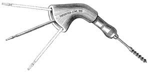
An adjustable angular bit stock patented June 25, 1861, by John F. Cory that incorporates a pair of universal joints within its casing. Equipped with Amidon's jaws.
Examples with green-enameled casing have been observed.
The patent drawings depict a mechanism integral to a standard bit brace rather than the independent attachment illustrated in the Millers Falls Company catalog. Dates referenced in table apply only to those years the tool was sold by Millers Falls.
Illustration from 1874 catalog.
| Model No. | Sweep | Start Date | End Date |
|---|---|---|---|
| Unnumbered | n/a | ca. 1873 | ca. 1878 |
Unnumbered (Patented)
Patented Universal Angular Bit Stock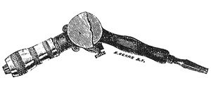
An adjustable angular bit stock. Equipped with Amidon's jaws.
Patent not located. Dates referenced in table apply only to those years the tool was sold by Millers Falls.
Illustration from 1878 catalog.
| Model No. | Sweep | Start Date | End Date |
|---|---|---|---|
| Unnumbered | n/a | ca. 1878 | ca. 1882 |
Unnumbered (Anthoine)
Anthoine's Universal Angular Bit Stock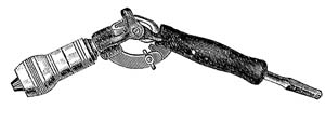
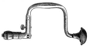
Single universal joint; adjustment mechanism consists of slotted overlapping pieces of sheet metal with lockable thumb screw; bright parts nickel plated; Amidon's jaws.
Patented December 21, 1875, by James W. Anthoine. On some examples, the mechanism displays the patent date when device is in the 180-degree position. Superseded by the No. 109 universal angular bit stock.
Used with bit brace or breast drill as an extension or angular borer.
Illustration from 1884 catalog.
| Model No. | Sweep | Start Date | End Date |
|---|---|---|---|
| Unnumbered | n/a | ca. 1882 | 1897 |
Nos. 0 - 4 (Barber Imp'd)
Barber Improved Brace, non-ratcheting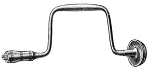
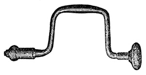
- 1868 —Wrought iron frame; socket forged in place; wrist formed by thickening of sweep; lignam vitae head; Amidon's jaws.
- ca. 1871 — as above, but socket is an attachment; lignam vitae head.
- 1878 — steel sweep.
Variant: Rose-pattern wrist handles have been observed.
Earliest models stamped G & A, for Gunn and Amidon. Illustration from 1874 catalog.
| Model No. | Sweep | Start Date | End Date |
|---|---|---|---|
| No. 0 | 14 inch | ca. 1870 | ca. 1881 |
| No. 1 | 12 inch | 1868 | ca. 1881 |
| No. 2 | 10 inch | 1868 | ca. 1881 |
| No. 3 | 8 inch | 1868 | ca. 1881 |
| No. 4 | 6 inch | 1868 | ca. 1881 |
Nos. 0-4 (Goodell)
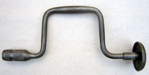
- 1868 — wrought iron frame; socket forged in place; wrist formed by thickening of sweep; metallic head; Goodell's chuck.
- ca. 1871 — as above, but socket is an attachment; lignam vitae head.
The brace pictured here is an early example and may have been manufactured by Albert and Henry Goodell at their factory in Buckland, Massachusetts. Millers Falls Mfg. acquired the patent for the Goodell brace ca. 1870. For a similar brace, see Nos. 10-14 (Goodell).
More information on the Goodell brace. Author's photo of ca. 1868 brace.
| Model No. | Sweep | Start Date | End Date |
|---|---|---|---|
| No. 0 | 14 inch | ca. 1870 | ca. 1874 |
| No. 1 | 12 inch | 1868 | ca. 1874 |
| No. 2 | 10 inch | 1868 | ca. 1874 |
| No. 3 | 8 inch | 1868 | ca. 1874 |
| No. 4 | 6 inch | 1868 | ca. 1874 |
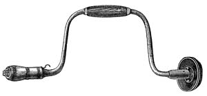
Nos. 0 - 5 (Rose)
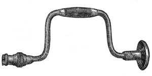
- ca. 1868 — wrought iron frame; metallic head; Rose pattern wrist handle (rosewood); Rose patent chuck.
- ca. 1874 — as above, but lignum vitae head; rotating wrist handle; brass rings in wrist handle to prevent splitting.
Originally manufactured by the Bit Stock Company of Greenfield, Mass., the Millers Falls Mfg. Company began producing the braces ca. 1870.
More information on the Rose brace. Illustration from 1874 catalog.
| Model No. | Sweep | Start Date | End Date |
|---|---|---|---|
| No. 0 | 14 inch | ca. 1870 | ca. 1878 |
| No. 1 | 12 inch | ca. 1868 | ca. 1878 |
| No. 2 | 10 inch | ca. 1868 | ca. 1878 |
| No. 3 | 8 inch | ca. 1868 | ca. 1878 |
| No. 4 | 6 inch | ca. 1868 | ca. 1878 |
| No. 5 | 5 inch | ca. 1868 | ca. 1878 |
No. 040
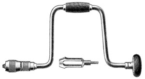 Car Shop & Ship-Carpenter's Brace
Massive, 16 inch sweep of 5/8 inch diameter steel; ball bearing head; heavy duty chuck with Barber's jaws.
A brute of a brace, built to withstand extreme strain without becoming sprung. This may be the brace referred to by employee Ray Bartlett when speaking of a special government order “for braces with a 16-inch sweep used in ship building together with big ship augers—two to three inches in diameter and 48 inches long.”
“Ray Bartlett Knows the History of Many Early MF Tools.” In special supplement: A Century of Experience: Millers Falls Company. In: Greenfield Record, Gazette and Courier, August 13, 1968.
Illustration from 1910 catalog.
| Model No. | Sweep | Start Date | End Date |
|---|---|---|---|
| No. 040 | 16 inch | 1910 | 1912 |
Nos. 1 - 2 (Lynam)
Wrought iron frame; wrist formed by thickening of sweep; lignum vitae head; ratchet activated by a thumbscrew that moves a flat spring allowing for clockwise or counterclockwise rotation; Amidon's jaws.
When the company's ring shifter/ratchet dog models became predominant, the Lynam brace disappeared from the line. Patented on December 5, 1871 by John T. Lynam of Jefferson, Indiana.
More information on the Lynam brace. Illustration from 1874 catalog.
| Model No. | Sweep | Start Date | End Date |
|---|---|---|---|
| No. 1 | 12 inch | 1871 | ca. 1881 |
| No. 2 | 10 inch | 1871 | ca. 1881 |
Nos. 1 - 4 (Barber)
Wrought iron frame; wrist formed by thickening of sweep; lignum vitae head; Barber's jaws.
The original Barber brace, it may be marked G & A, the initialism for pre-Millers Falls manufacturer Gunn and Amidon, or G. A. & S., for Gunn, Amidon & Saxton.
More information on the original Barber brace. Illustration from ca. 1867 New-England Business Directory.
| Model No. | Sweep | Start Date | End Date |
|---|---|---|---|
| No. 1 | 12 inch | 1864 | ca. 1870 |
| No. 2 | 10 inch | 1864 | ca. 1870 |
| No. 3 | 8 inch | 1864 | ca. 1870 |
| No. 4 | 4 inch | 1868 | ca. 1870 |
Nos. 1-4 (Eyebolt)
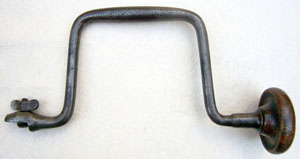
- 1867 — wrought iron frame; wrist formed by thickening of sweep; hardwood head; eyebolt/wingnut assembly holds bit in place.
- 1871 — as above, but lignum vitae head.
- ca. 1874— as above, but maple head and wrist handle.
More information on the Amidon eyebolt brace. Author's photo of ca. 1867 brace.
| Model No. | Sweep | Start Date | End Date |
|---|---|---|---|
| No. 1 | 12 inch | 1867 | ca. 1874 |
| No. 2 | 10 inch | 1867 | ca. 1878 |
| No. 3 | 8 inch | 1867 | ca. 1878 |
| No. 4 | 6 inch | 1867 | ca. 1874 |
Nos. 10 - 14 (Goodell)
Wrought iron frame, lignum vitae head; rosewood wrist handle; brass rings in wrist handle to prevent splitting; Goodell's chuck.
Millers Falls Mfg. acquired the patent for the Goodell brace ca. 1870. Prior to this time it may have been manufactured by Albert and Henry Goodell in Buckland, Massachusetts. For a similar version, see No. 0-4 (Goodell).
More information on the Goodell brace. Author's photo of ca. 1875 brace.
| Model No. | Sweep | Start Date | End Date |
|---|---|---|---|
| No. 10 | 14 inch | ca. 1871 | ca. 1878 |
| No. 11 | 12 inch | ca. 1871 | ca. 1878 |
| No. 12 | 10 inch | ca. 1871 | ca. 1878 |
| No. 13 | 8 inch | ca. 1871 | ca. 1878 |
| No. 14 | 6 inch | ca. 1871 | ca. 1878 |
Nos. 10 - 14 (Rose)
Wrought iron frame, wrist formed by thickening of sweep; lignum vitae head; Rose patent chuck.
For a similar version, see No. 0-5 (Rose).
More information on the Rose brace. Author's photo of ca. 1876 brace.
| Model No. | Sweep | Start Date | End Date |
|---|---|---|---|
| No. 10 | 14 inch | ca. 1875 | ca. 1878 |
| No. 11 | 12 inch | ca. 1875 | ca. 1878 |
| No. 12 | 10 inch | ca. 1875 | ca. 1878 |
| No. 13 | 8 inch | ca. 1875 | ca. 1878 |
| No. 14 | 6 inch | ca. 1875 | ca. 1878 |
Nos. 10 - 16; 10A-15A
(Model nos. designated 'A' were equipped with a steel clad, ball bearing head.)
- ca. 1871 — wrought iron frame; lignum vitae head; with Rose pattern wrist handle (rosewood); Amidon's jaws.
- 1878 — as above, but steel frame; McCoy's rotating wrist handle; brass rings in wrist handle to prevent splitting; nickel plating.
- 1890 — as above, but McCoy's jaws.
- 1894 — as above, but rosewood head rides on ball bearings.
- 1899 — as above, but spring-type alligator jaws.
- 1905 — as above, but cocobolo head and handle.
- 1910 — as above, but wrist handle rides on adjustable bearings.
- 1914 — as above, but head and handle are tropical hardwood.
- 1915 — as above, but wrist handle lacks adjustable bearings.
- 1917 — as above, but head and handle are native hardwood.
- 1922 — as above, but head and handle are again cocobolo.
Nos. 15, 15A, and 16 were never offered with ball bearing heads. No. 16 was equipped with the small chuck that the company used for adjustable tool holders and was intended for piano makers.
Illustration from 1915 catalog.
| Model No. | Sweep | Start Date | End Date |
|---|---|---|---|
| No. 10 | 14 inch | ca. 1875 | 1922 |
| No. 10A | 14 inch | 1912 | 1917 |
| No. 11 | 12 inch | ca. 1871 | 1922 |
| No. 11A | 12 inch | 1912 | 1917 |
| No. 12 | 10 inch | ca. 1871 | 1935 |
| No. 12A | 10 inch | 1912 | 1917 |
| No. 13 | 8 inch | ca. 1871 | 1933 |
| No. 13A | 8 inch | 1912 | 1917 |
| No. 14 | 6 inch | ca. 1871 | 1935 |
| No. 14A | 6 inch | 1912 | 1917 |
| No. 15 | 4 inch | ca. 1876 | 1922 |
| No.15A | 4 inch | 1912 | 1913 |
| No. 16 | 4 inch | ca. 1884 | 1899 |
Nos. 11 - 13 (Hildreth)
Wrought iron frame; Hildreth ratchet, rotating rosewood wrist handle; lignum vitae head; steel jaws.
No relationship to the quick-release brace patented by Royal S. Hildreth in 1870. Based on Henry L. Hildreth’s February 28, 1871, patent for a ratcheting screwdriver.
Illustration from ca. 1874 catalog.
| Model No. | Sweep | Start Date | End Date |
|---|---|---|---|
| No. 11 | 12 inch | ca. 1874 | ca. 1878 |
| No. 12 | 10 inch | ca. 1874 | ca. 1878 |
| No. 13 | 8 inch | ca. 1874 | ca. 1878 |
Nos. 20 - 24
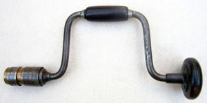
- ca. 1872 — wrought iron frame; hard maple head and handle; wrist handle is bulbous in shape; polished steel parts; Amidon's jaws. (Photo of this early brace)
- Note: out of production by 1878 and re-introduced in 1885.
- 1885 — steel frame; ebonized hardwood head and handle; wrist handle no longer bulbous.
- 1897 — as above, but stained hardwood head and handle.
- 1905 — as above, but ball bearing head; McCoy's jaws.
- 1912 — as above, but spring-type alligator jaws.
- 1917 — as above, but anti-friction washer in head.
- 1922 — as above, but metallic rings in wrist handle prevent splitting.
A mid-priced brace, it could be ordered with an octagonal chuck shell, 1912-1915.
Illustration from 1915 catalog.
| Model No. | Sweep | Start Date | End Date |
|---|---|---|---|
| No. 20 | 14 inch | 1912 | 1925 |
| No. 21 | 12 inch | ca. 1872 | 1929 |
| No. 22 | 10 inch | ca. 1872 | 1929 |
| No. 23 | 8 inch | ca. 1872 | 1929 |
| No. 24 | 6 inch | 1915 | 1917 |
Nos. 30 - 34; 30A - 34A
- Barber Ratchet Brace, 1874-1879
- A Barber Improved Ratchet Brace, 1879-1947
(Model nos. designated 'A' were equipped with a steel clad, ball bearing head.)
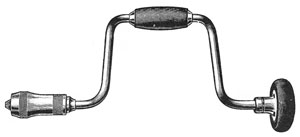
- 1874— wrought iron frame; half-boxed ratchet; lignum vitae head; rosewood wrist handle; Barber's jaws.
- ca. 1878 — as above, but steel frame; brass rings in wrist handle to prevent splitting; nickel plating.
- 1879 — as above, but Amidon's jaws.
- 1890 — as above, but McCoy's jaws.
- 1894 — as above, but fully boxed ratchet, rosewood head rides on ball bearings; steel washer between ratchet and chuck sockets.
- 1899 — as above, but spring-type alligator jaws.
- 1905 — as above, but cocobolo head and handle.
- 1910 — as above, but wrist handle rides on adjustable bearings.
- 1914 — as above, but head and handle of tropical hardwood.
- 1915 — as above, but wrist handle lacks adjustable bearings.
- 1917 — as above, but cocobolo head and handles.
- 1935 — as above, but head and handle of tropical hardwood; all models with a steel clad, ball bearing head.
- 1949 — as above, but 'toothless' alligator jaws.
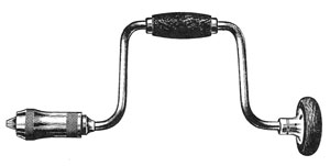
Illustration from 1915 catalog.
| Model No. | Sweep | Start Date | End Date |
|---|---|---|---|
| No. 30 | 14 inch | ca. 1884 | 1942 |
| No. 30A | 14 inch | 1912 | 1933 |
| No. 31 | 12 inch | 1874 | 1955 |
| No. 31A | 12 inch | 1912 | 1933 |
| No. 32 | 10 inch | 1874 | 1955 |
| No. 32A | 10 inch | 1912 | 1933 |
| No. 33 | 8 inch | 1874 | 1955 |
| No. 33A | 8 inch | 1912 | 1933 |
| No. 34 | 6 inch | 1899 | 1947 |
| No. 34A | 6 inch | 1912 | 1933 |
Nos. 40 - 44
- 1879 — lignum vitae head; rosewood wrist handle; brass rings in rotating wrist handle prevent splitting; nickel plating; Barber's jaws.
- 1880 — Stevens' sleeve added to Barber's jaws.
- 1894 — as above, but rosewood head rides on ball bearings.
- 1905 — as above, but cocobolo head and handle.
- 1914 — as above, but tropical hardwood head and handle.
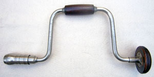
Out of production 1881-ca. 1884. Unwilling to commission new art work, the Millers Falls Company used an outdated woodcut dating from the early 1870s to represent this brace in its catalogs until at least 1887. The illustration bore no resemblance to the actual tool.
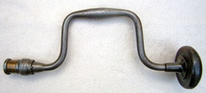
Author's photo of ca. 1885 brace.
| Model No. | Sweep | Start Date | End Date |
|---|---|---|---|
| No. 40 | 14 inch | 1880 | 1915 |
| No. 41 | 12 inch | 1879 | 1915 |
| No. 42 | 10 inch | 1879 | 1915 |
| No. 43 | 8 inch | 1879 | 1915 |
| No. 44 | 6 inch | 1880 | 1915 |
