Albert D. Goodell's Secondary Grip
On December 13, 1887, Albert D. Goodell was issued United States Letters Patent No. 374,594 for a drill chuck fitted with a T-shaped adjustable seat that put additional pressure on the back side of a pair of jaws as the chuck is tightened. The extra pressure was considered especially useful in keeping round-shanked bits from slipping during the drilling process. Goodell assigned the patent to his employer, the Millers Falls Company, and the company marketed his improvement as a secondary grip. Shortly after patenting his invention, he left Millers Falls to set up a tool company with his younger brother Henry.
The grip on a cast frame
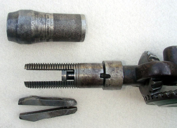
The No. 12 breast drill below is equipped with Goodell's secondary grip. As its chuck shell is tightened, a T-shaped seat is forced against the rear of the jaws by the drill's spindle. A small, spring-loaded catch—designed to prevent the top nut and socket from disengaging as the chuck shell is loosened—is missing on this example. The catch is activated whenever the notches in the socket and nut are aligned. When functioning properly, the drill's secondary grip moves into and out of place automatically as the chuck is adjusted and requires no conscious effort on the part of the user. The presence of William H. McCoy's self-opening jaws indicates that this particular drill was manufactured between 1890 and the abandonment of the secondary grip in 1896.
Photos by author.


The grip on a rod-type frame
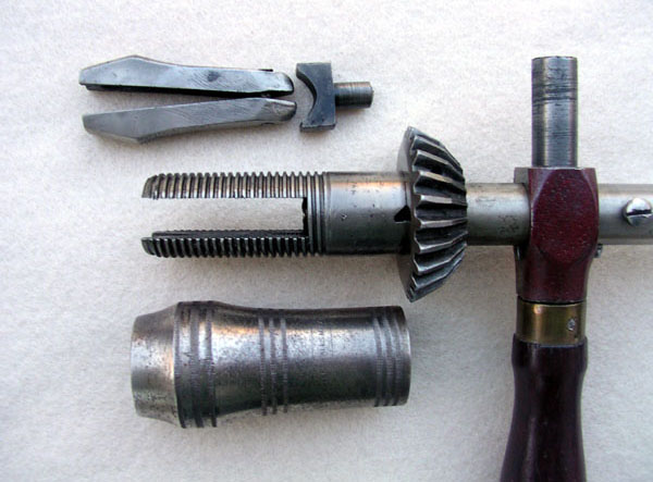
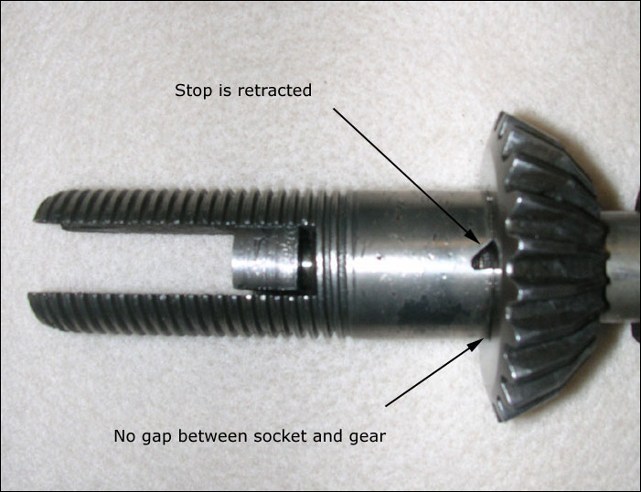
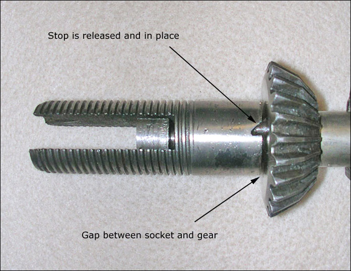
Pictured below is Goodell's secondary grip on a No. 10 breast drill. On this example, the T-shaped adjustable seat is contoured to conform to Amidon's jaws, and the design of the drill's rod-type frame renders the top nut superfluous. The small triangular notch at the top of the socket activates the spring-loaded catch that prevents accidental rotation of the socket as the chuck shell is loosened. After a long period of inactivity, drills equipped with this iteration of Goodell's secondary grip require a good deal of cleaning in order to function properly since sockets and catches are often frozen in place by hardened grease. (The spring-loaded catch is labeled as a 'stop' in the images below).
The second photo shows the position of the socket when no forward pressure is exerted on the plunger. The third photo shows the position of the socket when the plunger is pushed forward. The lightly knurled chuck shell and presence of Amidon's jaws indicate that the drill seen here was manufactured between 1887 and 1890.
Photos by author.
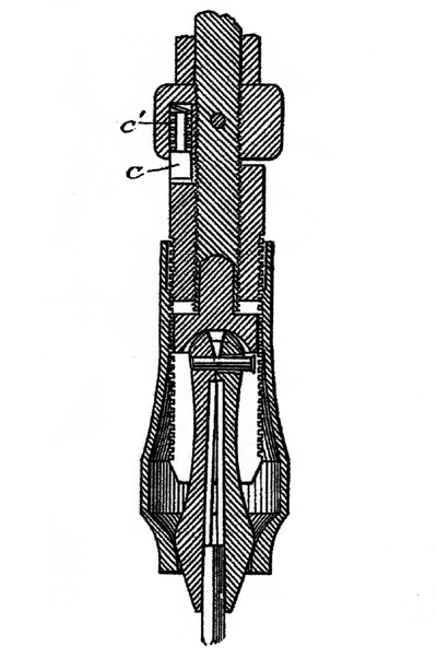
Patent drawings
These drawings formed part of Goodell's application for a patent for his grip. The spring loaded catch is labeled c; the spring itself is labeled c'. The chuck is depicted with Amidon's jaws. The illustrations have been modified to improve legibility